 TheCircuitDog
How Backfeeding Happens Through I/O and ESD Structures
One powered rail can energize a supposedly unpowered rail through signal-pin protection structures, pull-ups or output drivers.
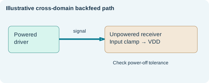
Why an unpowered rail may not be zero
Many I/O pins contain ESD clamp structures to the supply rails. Depending on the device, a signal voltage applied while VDD is off can source current into the supply node. Never assume a device is power-off tolerant without checking the datasheet.
Common paths in mixed-power boards
Comparators with pull-up networks, GPIO from a powered domain, ADC front-end op-amps, level shifters and JTAG interface pins are common suspects. Also check analog paths with input voltages above the powered-down amplifier rails.
Methodical isolation
Record suspect rail voltages with each upstream supply enabled individually, under conditions allowed by the device documentation. Look for a correlation between a signal source turning on and the unpowered rail rising.
Mitigation options
Depending on system constraints, use power-off-tolerant buffers, isolation switches, series resistance sized within injection-current limits, appropriate sequencing or supply-domain changes.
Practical checklist
- Consult absolute maximum and injection-current specifications.
- Identify always-on pull-ups.
- Check each cross-domain I/O.
- Avoid driving signals into an unpowered device outside its specified limits.
- Document which rail can energize which node.