 TheCircuitDog
Decoupling Capacitors: Placement and Selection
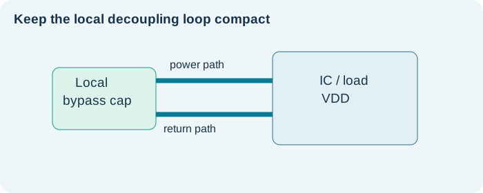
Decoupling is an electrical loop problem as much as a capacitance problem. A small capacitor very close to a supply pin can be more effective at high frequency than a larger one farther away.
Separate local bypass from bulk storage
High-frequency bypass capacitors provide a short current loop for edge events; bulk capacitance supports slower load changes and helps the regulator handle transients.
Place the high-frequency loop first
Connect power pin to capacitor pad and ground return with low inductance. Short traces and adjacent reference planes are usually valuable. Check the IC manufacturer’s layout example.
Consider real MLCC behavior
Ceramic capacitance can change with DC bias, temperature, voltage rating, aging and dielectric. The effective capacitance on a 3.3 V rail can be substantially less than the label value.
Regulator stability is separate
LDOs and switching regulators may require a specific output capacitance and ESR range. Use the regulator datasheet rather than assuming any capacitor network is stable.
Practical checklist
- List each IC rail and nearby capacitors.
- Review MLCC DC-bias curves.
- Follow regulator capacitor/ESR constraints.
- Inspect ground return paths.
- Measure supply ripple near the device pins.