 TheCircuitDog
Choosing Power-Good Pull-Ups
A pull-up resistor on a PGOOD output is not just a formality: it determines rise time and the current the driving transistor must sink.
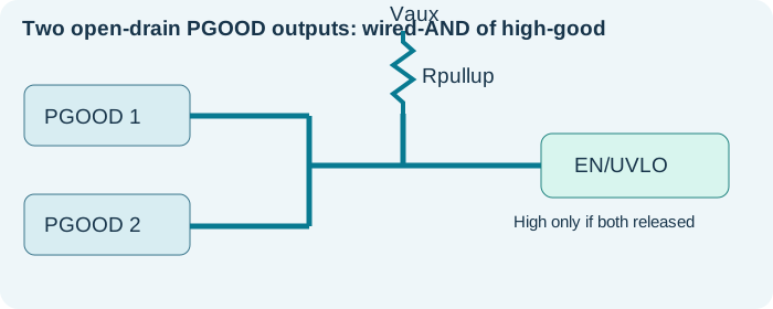
Open drain versus push-pull
An open-drain output can pull the line low, but it depends on an external pull-up to reach logic high. A push-pull output should not be tied directly to another push-pull output; the drivers may contend.
Choose resistance from current and timing
Low-state sink current is approximately Vpullup/Rpullup. For an ideal 3.3 V pull-up, 100 kΩ corresponds to roughly 33 µA and 4.7 kΩ to roughly 0.7 mA. The actual low voltage and allowable current depend on the device datasheet.
Rise time is an RC problem
The high-going edge is controlled by the pull-up and the total line capacitance. As a useful approximation, 10–90% rise time is about 2.2 × Rpullup × Cnode. A long trace, many inputs or a 100 kΩ resistor may yield an unexpectedly slow enable transition.
Check the destination pin
EN/UVLO pins can include internal bias, hysteresis and thresholds that differ from standard CMOS input levels. Measure the actual pin voltage and check it against the regulator’s enable thresholds.
Practical checklist
- Know whether PGOOD is open-drain or push-pull.
- Confirm pull-up voltage is allowed for the output pin.
- Check sink current and worst-case VOL.
- Estimate node capacitance and rising-edge time.
- Scope EN/UVLO and PGOOD simultaneously.