 TheCircuitDog
Power Sequencing and PGOOD Logic
When one supply enables another through PGOOD, the important signals are the actual voltage waveforms—not the appearance of a status LED.
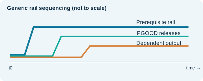
Start by defining the expected sequence
Make a rail-order table with nominal voltages, turn-on dependencies, tolerance limits and timing constraints. Record whether each PGOOD is active-high push-pull or an open-drain output that only sinks current. An open-drain “high” is supplied by an external pull-up, not driven by the IC.
Wired logic needs the correct polarity
Two open-drain active-high PGOOD outputs can be tied together with one pull-up to create a wired-AND of “good” conditions: the node rises only when neither output sinks. Verify that each output is genuinely open-drain, shares compatible voltage domains and has an allowed pull-up voltage.
Scope power-up rather than relying on steady-state LEDs
Capture upstream power, PGOOD outputs, the tied logic node, EN/UVLO at the regulator pin, and the dependent output rail during the same startup event. Look for pulse widths, slow rising edges, partial voltage and chatter that a DMM can miss.
Separate the logic path from regulator operation
With documented component limits and a safe bench procedure, determine whether the regulator can run with its enable driven from a known-valid signal. Do not hard-short a pin to a supply rail without checking its allowed voltage and sequencing requirements.
Practical checklist
- Record PGOOD pull-up destination and resistance.
- Verify signal low/high thresholds from both datasheets.
- Measure EN directly at the device pad during startup.
- Check for unintended feedback/backfeeding into an unpowered device.
- Reconfirm rail order and ramp rate against the FPGA/ASIC requirements.